NOVATEUR PUBLICATIONS
INTERNATIONAL JOURNAL OF INNOVATION IN ENGINEERING, RESEARCH AND TECHNOLOGY [IJIERT]
NATIONAL CONFERENCE ON INNOVATIVE TRENDS IN ENGINEERING & TECHNOLOGY-2016
11TH & 12TH MARCH 2016
CONFERENCE PROCEEDINGS ISSN NO – 2394-3696
Paper ID: NITETCIVIL04
USE OF MECHANICAL SPLICES FOR REINFORCING STEEL
Swami P. S.
Department of Civil Engineering, Solapur University, Solapur, Maharashtra, India
[email protected]
Javheri S. B.
Department of Civil Engineering, Solapur University, Solapur, Maharashtra, India
[email protected]
Mittapalli D. L
Department of Civil Engineering, University of Pune, Pune, Maharashtra, India
Kore P. N.
Department of Civil Engineering, Solapur University, Solapur, Maharashtra, India
[email protected]
ABSTRACT
Lap splicing requires the overlapping of two parallel bars. The overlap load transfer mechanism takes advantage of the bond between the steel and the concrete to transfer the load. The load in one bar is transferred to the concrete, and then from the concrete to the ongoing bar. The bond is largely influenced by deformations (ribs) on the surface of the reinforcing bar. Lap splices, then, can be considered structurally less reliable and design-constrictive, with many ‘hidden’ costs. As a result, usage of mechanical splices previously considered cost-prohibitive is on the rise. Also mechanical splice (Couplers) offer added benefits. The coupler splices are more reliable than lap splices because they do not depend on concrete for load transfer. Superior cyclic performance and greater structural integrity during manmade, seismic or other natural events are other advantages of mechanical butt splices. Mechanical splicing does away with the tedious calculations needed to determine proper lap lengths, and their potential errors. Because mechanical splices do not overlap, less rebar is used, reducing materials costs. This paper verifies the strength of different couplers and also an economic viability study. Different types of samples were tested under UTM and the reports are studied to calculate the economic cost comparison of the same.
INTRODUCTION
Lap splicing, which requires the overlapping of two parallel bars, has long been accepted as an effective, economical splicing method. Lap splicing has become the traditional method of connecting the steel reinforcing bars. Splicing the Reinforcement bars by laps or welding have various imperfections such as low quality welds, inadequate length of laps, failure in joints, and increase in labour cost etc. Lapped joints are not always an appropriate means of connecting reinforcing bars. The use of laps can be time consuming in terms of design and installation and can lead to greater congestion within the concrete because of the increased amount of rebar used. Laps double the steel/concrete ratio and create problems while placing the bar and during concrete consolidation. Lap splices depend upon concrete for strength so they lack structural integrity and continuity in construction.
Couplers especially threaded one can simplify the design and construction of reinforced concrete structure and reduce the amount of reinforcement required. The coupler system is designed to connect two pieces of rebar together in the field quickly and easily. Mechanical splicing assures the maintaining of the continuity of the load path in the reinforcement, independent of the condition of concrete. Using mechanical butt splices allows the option of using larger diameter rebar in a smaller column, while minimizing congestion. Reduced column size results in a more efficient optimum use of floor space, an extremely beneficial from economic and design consideration. The reinforcement couplers not only provide strength to the joints but they are also an economic means of connections of two bars. Mechanical splice can bear and can deform more than a lap splice before failure occurs. The purpose of this study is to determine whether the mechanical splice sections are suitable as connectors and to study the strength and behaviour of Mechanical Splice (Coupler) under tensile loading and to study the present economic viability of this splicing system.
Performance of evaluation of mechanical joints of reinforcing bars (Yoshikazu Kanoh, Hiroshi Imai, Yaszhiro Matsuzaki and Shunsuke Sugano, 1988). Economic butt splices vs. lap splicing in reinforced concrete
1 | P a g e w w w . i j i e r t . o r g
NOVATEUR PUBLICATIONS
INTERNATIONAL JOURNAL OF INNOVATION IN ENGINEERING, RESEARCH AND TECHNOLOGY [IJIERT]
NATIONAL CONFERENCE ON INNOVATIVE TRENDS IN ENGINEERING & TECHNOLOGY-2016
11TH & 12TH MARCH 2016
CONFERENCE PROCEEDINGS ISSN NO – 2394-3696
construction (James R. Cagley, Richard Applr, 1997). Feasibility grouted splice connector under tensile loads (Ling Jen Hua, Ahmad Baharuddin Abd. Rahman, Izni Syahrizal Ibrahim, 2013). Reinforcement couplers as an alternative to lap splice (Singh R., Himanshu S. K., Bhalla N., 2013).
TYPES OF COUPLER
The coupler system is available in several styles to meet virtually any application. The applications include standard bar-to-bar connections, presaging applications, hooked bar applications, closure pours, precast connections, rebar terminations and anchorages, transition splices, segmental construction and connections to structural steel. For study purpose threaded coupler is adopted.
THREADED COUPLER
A common older interlock system is the threaded coupler as shown in Figure 1. With an ordinary system of threading, it is common to dress the ends of the rebar before cutting or rolling the threads, thereby reducing nominal bar area and lowering load capacity. There is little or no strength difference between cut and rolled threads of the same size. Rebar ends may generally be threaded either in the fabricator’s shop or in the field. Threaded bar ends must be protected against damage during shipping and handling until the splices are completed.
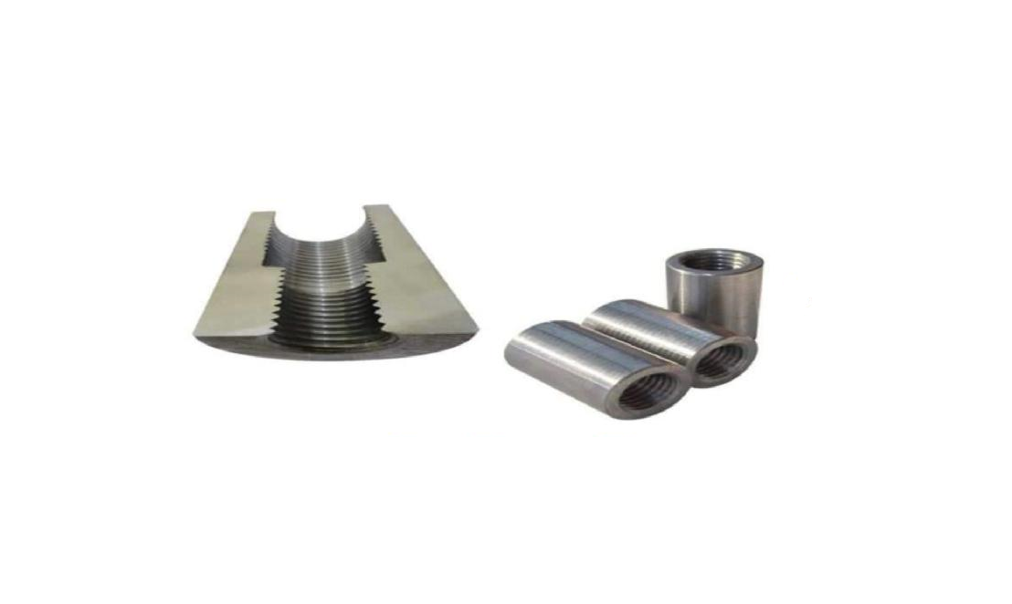 Figure 1: Typical threaded splice system
STEPS FOR PREPARING MECHANICAL JOINT
True joint (TJ-09) machine as show in Figure 2 is used to make threads on reinforcement steel bars. It can process Fe 500 and Fe 500D reinforcement steel bars with diameter 14 to 40 mm. The couplers are installed using following four steps:
a. The coupler is normally supplied to a reinforcing bar, ready to be installed and cast in concrete.
b. After casting of the concrete and when ready to extend, remove the plastic end cap from the coupler, position the continuation bar in the sleeve and rotate the bar into the coupler.
c. Continue to screw the bar into the coupler until tight and
d. To ensure correct installation, tighten the joint to the specified torque using a calibrated torque wrench on the continuation bar.
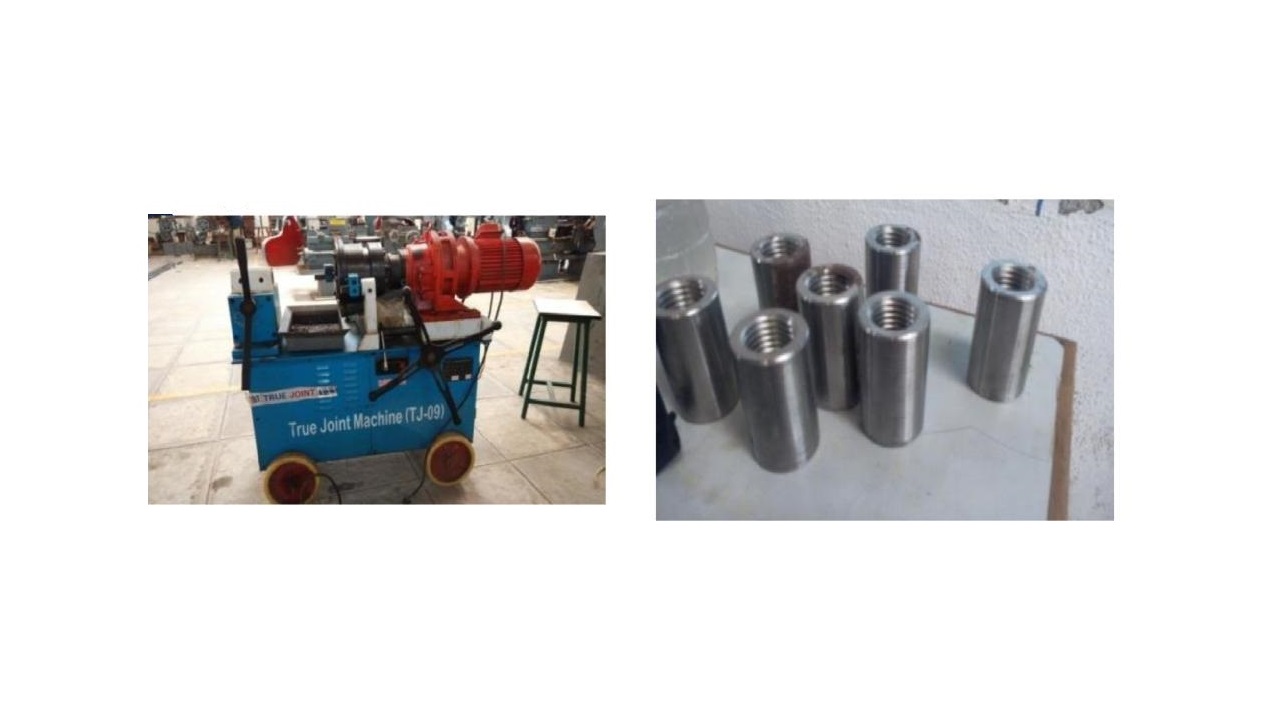 Figure 2: True joint (TJ-09) machine Figure 3: Mechanical Threaded Couplers
2 | P a g e w w w . i j i e r t . o r g
NOVATEUR PUBLICATIONS
INTERNATIONAL JOURNAL OF INNOVATION IN ENGINEERING, RESEARCH AND TECHNOLOGY [IJIERT]
NATIONAL CONFERENCE ON INNOVATIVE TRENDS IN ENGINEERING & TECHNOLOGY-2016
11TH & 12TH MARCH 2016
CONFERENCE PROCEEDINGS ISSN NO – 2394-3696
MECHANICAL THREADED COUPLER
Couplers are manufactured on a metal lathe machine. It rotates the work piece on its axis to perform various operations such as cutting, sanding, knurling, drilling, or deformation with tools that are applied to the work piece to create an object which has symmetry about an axis of rotation. A very important aspect of coupler selection is selection of material and specifications given for them as shown in Table 1. Each manufacturer gives its own specification regarding coupler selection. It includes specifications of a leading foreign coupler manufacture and Indian specification for the selection of couplers given by NCT (National Cutting Tools). Generally couplers are manufactured from Mild Steel, but in some cases alloys of different metals can also be used as show in Figure 3. The material should be such that couplers meet the minimum strength requirement (125% of yield strength of rebar).
Table 1. Specifications of Coupler
Coupler External Internal
Diameter Diameter Diameter Length Pitch
(mm) (mm) (mm) (mm) (mm)
16 19.32 14.5 40.8 1.5
20 31.00 18.7 50.0 1.9
25 37.30 23.0 60.9 2.0
40 59.00 37.8 91.0 2.2
DUCTILE BEHAVIOUR OF MECHANICALLY SPLICED COUPLERS
It is depicted that the ductility of RC beam reduced when using mechanical splices. There are some factors affect the ductile behaviour of the beams can be seen:
a. Strength of mechanical splices,
b. Staggering length of mechanical splices and
c. Epoxy injection into mechanical splices.
Mechanical Splices are commonly used in construction of reinforced concrete structures. It is a crucial issue for the structural engineers to determine what type of reinforcement splices should be used and where they should be located in the structures. The effect of epoxy injected in mechanical splices is increasing ductility, reducing crack width but does not increase the strength of the beam. Staggering length of the mechanical splices bar does not affect the strength of the beam but it will have a better cracking behavior and ductility if the staggering length is increased.
EXPERIMENTAL PROCEDURE
The materials used in this experimental work were Mechanical threaded coupler and HYSD Rebars (Fe 500). Fe 500 steel bars of diameters 12, 16, 25, 32 mm were used for study. All the steel bars used for experimentation are of same manufacturing company. Before actual start of work all steel specimens were tested in laboratory in order to check their stipulated property.
3 | P a g e w w w . i j i e r t . o r g
NOVATEUR PUBLICATIONS
INTERNATIONAL JOURNAL OF INNOVATION IN ENGINEERING, RESEARCH AND TECHNOLOGY [IJIERT]
NATIONAL CONFERENCE ON INNOVATIVE TRENDS IN ENGINEERING & TECHNOLOGY-2016
11TH & 12TH MARCH 2016
CONFERENCE PROCEEDINGS ISSN NO – 2394-3696
Table 2. Average comparative results of 16 mm, 25 mm and 32 mm diameter rebar for splicing
Samples: I, II and III Normal Bars (I, II & III) Coupled Bars (I, II & III) Welded Bars (I & II)
Identification Mark 16-TS 25-TS 32-TS 16-TS 25-TS 32-TS 16-TS 25-TS 32-TS
Nominal Diameter 16 25 32 16 25 32 16 25 32
(mm)
Average Effective
Cross Sectional Area 187.5 479.745 803.82 187.5 479.745 803.82 187.5 479.745 803.82
of test piece(mm2)
Mass/meter (kg/m) 1.54 3.766 6.31 1.54 3.766 6.31 1.54 3.766 6.31
Gauge length (mm) 200 200 200 200 200 200 200 200 200
a) Yield stress 583.74 654.79 579.283 551.667 553.620 540.960 528.875 533.875 526.275
Obtained(N/mm2)
b) Yield stress
Standard as per I.S. > 500
1786(N/mm2)
a)Ultimate stress 697.856 740.667 675.767 632.05 656.527 655.173 601.735 603.695 621.295
Obtained (N/mm2)
b)Ultimate stress
Standard as per I. S. > 545
1786(N/mm2)
Percentage Elongation 15.77 16.44 16.19 16.04 16.56 15.88 16.73 15.95 18.38
% % % % % % % % %
Distance of Fracture
from Center of NA NA NA 20.5 69.333 51.333 NA NA NA
Coupler (mm)
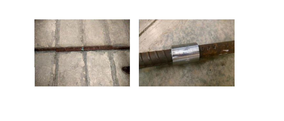 a) Welded Splice b) Coupler Splice
Figure 4: Couplers before Test
There are three basic ways to splice the bars i.e. Lap Splice, Welded Splice and Mechanical Splice. For comparison purpose an incremental tensile load tests were carried out on welded splices as shown in Figure 4 (a) and coupler splices and or mechanical splice as shown in Figure 4 (b). The results were analyzed as shown in Table 2 and the feasibility of the specimens was determined based on several evaluation criteria.
a) Failure of Welded Splice b) Failure of Coupler Splice
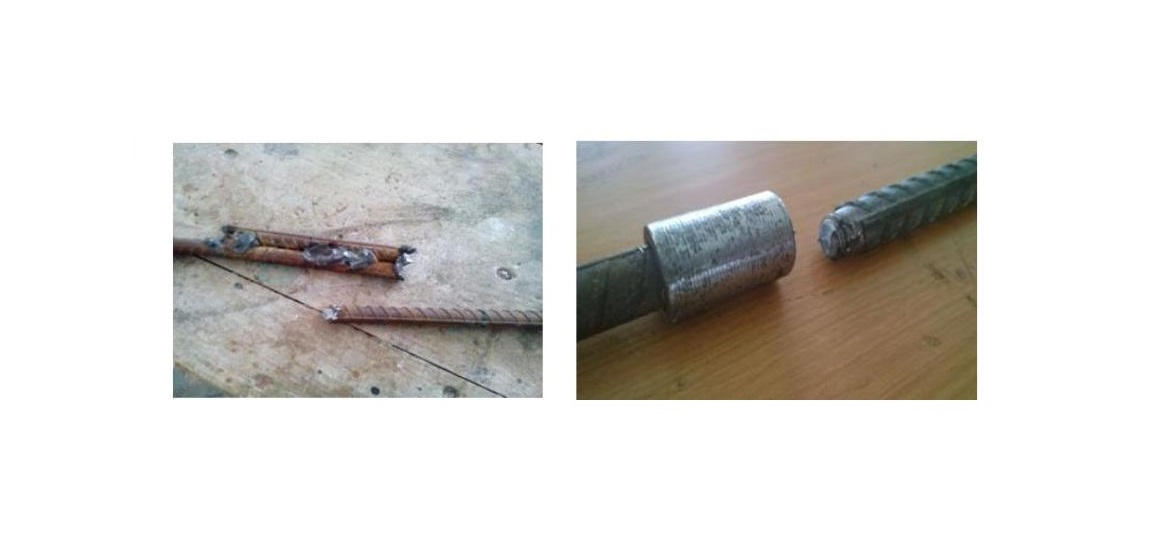 Figure 5: Couplers after Test
4 | P a g e w w w . i j i e r t . o r g
NOVATEUR PUBLICATIONS
INTERNATIONAL JOURNAL OF INNOVATION IN ENGINEERING, RESEARCH AND TECHNOLOGY [IJIERT]
NATIONAL CONFERENCE ON INNOVATIVE TRENDS IN ENGINEERING & TECHNOLOGY-2016
11TH & 12TH MARCH 2016
CONFERENCE PROCEEDINGS ISSN NO – 2394-3696
COST ANALYSIS
A cost has been computed based on saving of steel in lapping which indicates couplers are an effective and an economic replacement of lap splice. Table 3 shows how couplers have effectively saved a huge amount of money in a single joint. The total cost saved per joint for 25 mm rebar is Rs. 225/- and for 32 mm rebar is Rs. 499/- which is very less than what would have been spent if lapping would have been done by using site method or simply I.S. 456: 2000 specification. On the same line for 16 mm and 12 mm rebar the saving is comparatively less.
Mechanical splices add structural and economic advantages over laps make the benefit-to-cost ratio extremely attractive because mechanical splices give the structures added toughness and load path continuity that laps cannot offer. The reinforcement couplers not only provide strength to the joints but are they are also an economic means of connections of two bars.
Table 3. Cost Analysis (For M20 grade of concrete)
Bar Weight of Development Quantity Steel Cost of Total
Steel per of Steel
Diameter Length Saving Coupler Saving
meter Saved
(mm) (mm) Ld Rs Rs Rs
(kg/m) Kg
32 6.31 1925 12.189 609 /- 110/- 499/-
25 3.85 1416 5.545 285/- 60/- 225/-
16 1.58 910 1.432 74.45/- 40/- 34.45/-
12 0.89 680 0.68 31.48/- 25/- 6.48/-
Figure 6: Graph of Cost Analysis
CONCLUSIONS
This study shows that couplers are effective and economic replacement of lap splice and can save a huge amount of money in a single joint. The couplers were considerably more cost effective and time saving than welding the bars together. No special high strength, enlarged thread section or increased rebar size is necessary, thus allowing the supply of reinforced bar from multiple sources for maximum cost savings. The threaded splice is a widely used mechanical splicing system worldwide.
ACKNOWLEDGMENT
We highly indebted to Dr. S. A. HALKUDE (Principal, W. I. T., Solapur), Dr. S. S. PATIL (H.O.D. Civil Department) and Dr. B. B. DESHM (technical help) for giving us immense co-operation as well as for providing necessary information regarding in completing this work, “Use of Coupler Splices For Reinforcement”. We would also like to extend our sincere thanks to Mr. SANJAY GUPTA Managing Director of RUDRALI HI-TECH TOOLS PVT. LTD. for sponsor.
5 | P a g e w w w . i j i e r t . o r g
NOVATEUR PUBLICATIONS
INTERNATIONAL JOURNAL OF INNOVATION IN ENGINEERING, RESEARCH AND TECHNOLOGY [IJIERT]
NATIONAL CONFERENCE ON INNOVATIVE TRENDS IN ENGINEERING & TECHNOLOGY-2016
11TH & 12TH MARCH 2016
CONFERENCE PROCEEDINGS ISSN NO – 2394-3696
REFERENCES
[1] Harry B. Lancelot Studied, “Proprietary Couplers For Tension And Compression Splices: Ready and Able When Ordinary Lap Splices Aren’t Suitable”.
[2] Imai H. and Kanoh Y., “Standard for Performance Evaluation of Rabar Joint,” Seminar on Precast
Construction in Seismic Zones, Japan Concrete Institute, Vol. 2, 137-156, 1986.
[3] Yoshikazu Kanoh, Hiroshi Imai, Yaszhiro Matsuzaki and Shunsuke Sugano, “Performance of evaluation of mechanical joints of reinforcing bars”, Elsevier Ltd., 1988.
[4] James R. Cagley and Richard Apple, “Economic Analysis of Mechanical Butt Splices vs. Lap Splicing in
Reinforced Concrete Construction”, Rockville, Md., for Erico Inc., 1997.
[5] Ling Jen Hua, Ahmad Baharuddin Abd. Rahman, Izni Syahrizal Ibrahim Studied, “Feasibility of Grouted Splice Connector under Tensile Load”, Elsevier Ltd., 2013.
[6] Singh R., Himanshu S. K., Bhalla N., “Reinforcement couplers as an alternative to lap splices”,
International journal of Engineering & Technology, Vol. 2, 2013.
[7] I.S. 456-2000, Indian standard code of practice for plain and reinforced concrete (fourth revision), Bureau of Indian standards, New Delhi.
[8] John W. Wallace, “Headed Reinforcement a Viable Option,” Concrete International, ACI, December 1997.
[9] Vidmantas Jokūbaitis1, Linas Juknevičius, “Influence of Reinforcement Couplers on the Cracking of
Reinforced Concrete Members”.
[10] Russell S. Fling,” Practical Design of Reinforced Concrete”, John Wiley &Sons, New York, 1987.